2016年4月22日星期五

How to differentiate between ESP8266 Series module

ESP8266 系列模组是安信可(Ai-thinker)公司采用乐鑫ESP8266芯片开发的一系列wifi 模组模块。
ESP8266 series module developed by Ai-thinker adopts Espressif ESP8266 chip.

ESP8266 特性:
*802.11 b/g/n
*内置低功耗32位CPU:可以兼作应用处理器
*内置10 bit高精度ADC
*内置TCP/IP协议栈
*内置TR开关、balun、LNA、功率放大器和匹配网络
*内置PLL、稳压器和电源管理组件
*支持天线分集
*STBC、1x1 MIMO、2x1 MIMO
*A-MPDU、A-MSDU的聚合和0.4 s的保护间隔
*WiFi @ 2.4 GHz,支持 WPA/WPA2 安全模式
*支持STA/AP/STA+AP工作模式
*支持Smart Config功能(包括Android和iOS设备)
*SDIO 2.0、(H) SPI、UART、I2C、I2S、IR Remote Control、PWM、GPIO
*深度睡眠保持电流为10 uA,关断电流小于5 uA
*2 ms之内唤醒、连接并传递数据包
*802.11b模式下+20 dBm的输出功率
*待机状态消耗功率小于1.0 mW (DTIM3)
*工作温度范围:-40°C - 125°C
*通过 FCC, CE, TELEC, WiFi Alliance 及 SRRC 认证

ESP8266 Feature:
*802.11 b/g/n protocol
*Wi-Fi Direct (P2P), soft-AP
*Integrated TCP/IP protocol stack
*Integrated TR switch, balun, LNA, power amplifier and matching network
*Integrated PLL, regulators, and power management units
*+19.5dBm output power in 802.11b mode
*Supports antenna diversity
*Power down leakage current of < 10uA
*Integrated low power 32-bit MCU
*SDIO 2.0, SPI, UART
*STBC, 1x1 MIMO, 2x1 MIMO
*A-MPDU & A-MSDU aggregation & 0.4μs guard interval
*Wake up and transmit packets in < 2ms
*Standby power consumption of < 1.0mW (DTIM3)


超低功耗技术:
ESP8266EX专为移动设备、可穿戴电子产品和物联网应用设计,并与其他几项专利技术一起使机器实现 最低能耗。这种节能的构造以三种模式运行:激活模式、睡眠模式和深度模睡眠式。
ESP8266EX使用高端电源管理技术和逻辑系统调低非必需功能的功率,调控睡眠模式与工作模式之间的 转换,在睡眠模式下,其消耗的电流小于12 uA,处于连接状态时,其消耗的功率少于1.0 mW(DTIM=3) 或 0.5 mW (DTIM = 10)。
睡眠模式下,只有校准的实时时钟和watchdog处于工作状态。可以通过编程使实时时钟在特定的时间 内唤醒 ESP8266EX。
通过编程,ESP8266EX会在检测到某种特定情况发生的时候自动唤醒。ESP8266EX在最短时间内自动 唤醒,这一特征可以应用到移动设备的SOC上,这样SOC在开启Wi-Fi之前均处于低功耗待机状态。
为满足移动设备和可穿戴性电子产品的功率需求,ESP8266EX在近距离时可以通过软件编程减少PA的输 出功率来降低整体功耗,以适应不同的应用方案。

Ultra Low Power Technology:
ESP8266EX has been designed for mobile, wearable electronics and Internet of Things applications with the aim of achieving the lowest power consumption with a combination of several proprietary techniques. The power saving architecture operates mainly in 3 modes: active mode, sleep mode and deep sleep mode.By using advance power management techniques and logic to power-down functions not required and to control switching between sleep and active modes, ESP8266EX consumes about than 60uA in deep sleep mode (with RTC clock still running) and less than 1.0mA (DTIM=3) or less than 0.5mA (DTIM=10) to stay connected to the access point.
When in sleep mode, only the calibrated real-time clock and watchdog remains active. The real-time clock can be programmed to wake up the ESP8266EX at any required interval.
The ESP8266EX can be programmed to wake up when a specified condition is detected. This minimal wake-up time feature of the ESP8266EX can be utilized by mobile device SOCs, allowing them to remain in the low-power standby mode until Wi-Fi is needed.In order to satisfy the power demand of mobile and wearable electronics, ESP8266EX can be programmed to reduce the output power of the PA to fit various application profiles, by trading off range for power consumption.


主要应用领域:
智能家居
家庭自动化
智能插座、智能灯
网状网络
工业无线控制
婴儿监控器
网络摄像机
传感器网络
可穿戴电子产品
无线位置感知设备
安全ID标签
无线定位系统信号
ESP8266EX Applications
*Smart power plugs
*Home automation
*Mesh network
*Industrial wireless control
*Baby monitors
*IP Cameras
*Sensor networks
*Wearable electronics
*Wi-Fi location-aware devices
*Security ID tags
*Wi-Fi position system beacons

ESP8266系列模块现在主要包括以下类型:
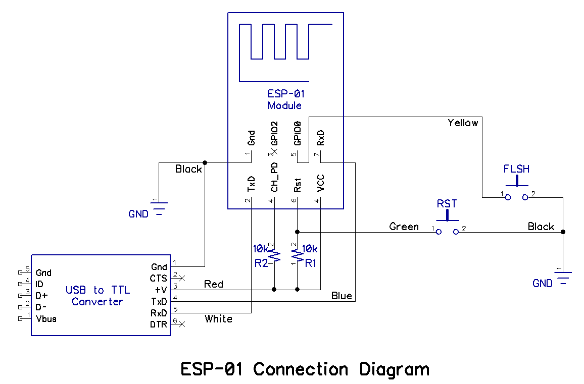
ESP-01 包括两个版本,一个是篮色版,一个是黑色版本的,功能一样,Pin脚一样,只是主板颜色不同,蓝色是老版产品,目前AI-thinker已经停产这种版本,但是市场上还是有一些在售产品,后期ESP-01都是黑色版本的。ESP-01 共接出 8 个接口 ,ESP-01 贴片式模组的外观尺寸为14.3mm*24.8mm*3mm。该模组采用的是容量为 1MB, 封装为SOP-210 mil 的 SPI Flash。模组使用的是3 DBi 的PCB 板载天线。

ESP8266 series modules As following types:
ESP - 01 includes two versions, one Blue version and a black version, functions and  Pin is same, only the mainboard.it is different the color of mainboard . the AI - thinker have shut down Blue version now, ESP-01 are altogether 8 pin counts, The external size of the module is 14.3mm*24.8mm*3mm .The type of Flash integrated in this module is an SPI flash, the capacity of which is 1 MB,the package size of  which is SOP-210mil.
The antenna applied on this module is a 3DBi PCB-on-board antenna.

ESP-02 共接出8个接口,ESP-02 贴片式模组的外观尺寸为 14.9mm*16.3mm *3mm。该模组采用的是容量为 1MB, 封装为 SOP-210 mil 的 SPI Flash。

ESP-02 are altogether 8 pin counts, The external size of the module is 14.9mm *16.3 mm *3mm .The type of Flash integrated in this module is an SPI flash, the capacity of which is 1 MB,the package size of  which is SOP-210mil.

ESP-03 共接出 14个接口,ESP-03 贴片式模组的外观尺寸为17.3mm*12.1mm*3mm。该模组采用的是容量为1MB, 封装为SOP-210 mil 的 SPI Flash。模组使用的是陶瓷板载天线。

ESP-03 are altogether 14 pin counts, The external size of the module is 17.3mm *12.1 mm *3mm .The type of Flash integrated in this module is an SPI flash, the capacity of which is 1 MB,the package size of  which is SOP-210mil.
The antenna applied on this module is a ceramic antenna.

ESP-04 共接出14个接口,ESP-04 贴片式模组的外观尺寸为 14.7mm*12.1mm *3mm。该模组采用的是容量为 1MB, 封装为 SOP-210 mil 的 SPI Flash。

ESP-04 are altogether 14 pin counts, The external size of the module is 14.7mm *12.1 mm *3mm .The type of Flash integrated in this module is an SPI flash, the capacity of which is 1 MB,the package size of  which is SOP-210mil.

ESP-05 共接出 5个接口,ESP-05 贴片式模组的外观尺为 14.2mm*14.2mm *3mm。该模组采用的是容量为 1MB, 封装为 SOP-210 mil 的 SPI Flash。

ESP-05 are altogether 5 pin counts, The external size of the module is 14.2mm *14.2 mm *3mm .The type of Flash integrated in this module is an SPI flash, the capacity of which is 1 MB,the package size of  which is SOP-210mil.

ESP-06共接出 20个接口,ESP-06E 贴片式模组的外观尺寸为 16.2mm*13.2mm *3mm。该模组采用的是容量为 1MB, 封装为 SOP-210 mil 的 SPI Flash。

ESP-06 are altogether 5 pin counts, The external size of the module is 16.2mm *13.2 mm *3mm .The type of Flash integrated in this module is an SPI flash, the capacity of which is 1 MB,the package size of  which is SOP-210mil.

ESP-7共接出16个接口,ESP-07 贴片式模组的外观尺寸为 16mm*21.2mm *3mm。该模组采用的是容量为 1MB, 封装为 SOP-210 mil 的 SPI Flash。配有陶瓷天线。

ESP-07 are altogether 5 pin counts, The external size of the module is 16mm *21.2 mm *3mm .The type of Flash integrated in this module is an SPI flash, the capacity of which is 1 MB,the package size of  which is SOP-210mil.
The antenna applied on this module is a ceramic antenna.

ESP-08共接出16个接口,ESP-08 贴片式模组的外观尺寸为 16mm*18.5mm *3mm。该模组采用的是容量为 1MB, 封装为 SOP-210 mil 的 SPI Flash。

ESP-08 are altogether 5 pin counts, The external size of the module is 16mm *18.5 mm *3mm .The type of Flash integrated in this module is an SPI flash, the capacity of which is 1 MB,the package size of  which is SOP-210mil.


ESP-09共接出 20个接口,ESP-09 贴片式模组的外观尺寸为 10mm*10mm *3mm。该模组采用的是容量为 1MB, 封装为 SOP-210 mil 的 SPI Flash。

ESP-09 are altogether 20 pin counts, The external size of the module is 10mm *10 mm *3mm .The type of Flash integrated in this module is an SPI flash, the capacity of which is 1 MB,the package size of  which is SOP-210mil.

ESP-10共接出 5个接口,ESP-10 贴片式模组的外观尺寸为 16mm*18.5mm *3mm。该模组采用的是容量为 1MB, 封装为 SOP-210 mil 的 SPI Flash。

ESP-10 are altogether 5 pin counts, The external size of the module is 16mm *18.5 mm *3mm .The type of Flash integrated in this module is an SPI flash, the capacity of which is 1 MB,the package size of  which is SOP-210mil.

ESP-11共接出 8个接口,ESP-11 贴片式模组的外观尺寸为 16mm*18.5mm *3mm。该模组采用的是容量为 1MB, 封装为 SOP-210 mil 的 SPI Flash。

ESP-11 are altogether 8 pin counts, The external size of the module is 16mm *18.5 mm *3mm .The type of Flash integrated in this module is an SPI flash, the capacity of which is 1 MB,the package size of  which is SOP-210mil.

ESP-12 共接出16  个接口,ESP-12 贴片式模组的外观尺?寸为 16mm*24mm *3mm。该模组采用的是容量为 4MB, 封装为 SOP-210 mil 的 SPI Flash。模组使用的是 3 DBi 的 PCB 板载天线。


ESP-12 are altogether 18 pin counts, The external size of the module is 16mm *18.5 mm *3mm .The type of Flash integrated in this module is an SPI flash, the capacity of which is 4 MB,the package size of  which is SOP-210mil.
The antenna applied on this module is a 3DBi PCB-on-board antenna.

ESP-12E 共接出 22 个接口,ESP-12E贴片式模组的外观尺寸为 16mm*24mm *3mm。该模组采用的是容量为 4MB, 封装为 SOP-210 mil 的 SPI Flash。模组使用的是 3 DBi 的 PCB 板载天线。

ESP-12E are altogether 16 pin counts, The external size of the module is 16mm *24 mm *3mm .The type of Flash integrated in this module is an SPI flash, the capacity of which is 4 MB,the package size of  which is SOP-210mil.
The antenna applied on this module is a 3DBi PCB-on-board antenna.

ESP-12F 共接出 22个个接口,ESP-12F 贴片式模组的外观尺寸为 16mm*24mm *3mm。该模组采用的是容量为 4MB, 封装为 SOP-210 mil 的 SPI Flash。模组使用的是 3 DBi 的 PCB 板载天线。

ESP-12F are altogether 18 pin counts, The external size of the module is 16mm *24 mm *3mm .The type of Flash integrated in this module is an SPI flash, the capacity of which is 4 MB,the package size of  which is SOP-210mil.
The antenna applied on this module is a 3DBi PCB-on-board antenna.

ESP-13 共接出 18 个接口,ESP-13 贴片式模组的外观尺寸为18mm*20mm *3mm。该模组采用的是容量为 4MB, 封装为 SOP-150 mil 的 SPI Flash。模组使用的是 3 DBi 的 PCB 板载天线。

ESP-13 are altogether 18 pin counts, The external size of the module is 18mm *20 mm *3mm .The type of Flash integrated in this module is an SPI flash, the capacity of which is 4 MB,the package size of  which is SOP-210mil.
The antenna applied on this module is a 3DBi PCB-on-board antenna.

ESP-14  共接出 22 个接口,ESP-14 贴片式模组的外观尺寸为16mm*24mm *3mm。该模组采用的是容量为1MB, 内置STM8003 MCU和ESP8266 WIFI芯片。ESP8266-14同时支持贴片和DIP插件两种方式,采用2.0的间隔 。

ESP-14 are altogether 18 pin counts, The external size of the module is 16mm *24 mm *3mm .the capacity of which is 1MB.ESP-14 module has a built-in powerful STMs8003F3P6 chips and wifi ESP8266, pick out all the pins, serial port can connected tthe serial port of the ESP8266, users can write STM8 program, through the AT command control WIFI Internet capability.

免费产品试用:
QQ :2154448623
Email :nicole@aithinker.com
Mob:13418538097
P.S.:Manufacturer export please direct contact with nicole@aithinker.com

2016年4月2日星期六

The battle of king for the Smart hardware Internet access points

The battle of king  for the  Smart hardware Internet access points 

The Internet can be regarded as a person's information, the Internet of things is the informatization of the world.
Internet of things is the basic function of a necessary access to the Internet, way outside WIFI and mobile GPRS data access two kinds.Once upon a time, the original rule out their own half of the world.But with the advent of the Internet of things intelligent household tuyere, especially as the price of dip, the market had the intersection!Such as mobile POS before, originally made with GPRS data access to the Internet, with the popularity of WIFI and hardware cost advantage, that was his WIFI grab the part of the market, the previous satellite receiver using GPRS module, some manufacturers began to use the WIFI module to replace.2 g basic being idle and GPRS, and as the GPRS module to reduce the cost of equipment, Moore's law, the threshold of the GPRS is expensive, is also a thing of the past.GPRS Internet access to the congenital advantage has been fully demonstrated.


Here are some professional advices to analyze market Demand for customer

Rate: WIFI is famous for its high data rate.It is second to Tony GPRS compared with WiFi.But the smart home and Internet data transmission volume is small, usually 1 k Byte/S basic will be enough.So in the Internet of things applications, speed is not bottleneck restriction.
Price: as the Internet WIFI module 24 months of continuous fighting, a quarter of the price is reduced to 2 years ago, basic!They will be done within 10 yuan.For Internet GPRS module, essence can adopt the same strategy: WIFI to activate the market first.Essence can launch the full spectrum of GPRS module again upset the market, focus on the Internet of things and smart home market, in 15 RMB retail price, batch test.The price is in line with the WIFI module on market!
Security: for router back door gust, zero day vulnerabilities, GPRS data flow security is quite high, the possibility of attack and be black small relative to the WIFI.
Traffic expenses: WIFI completely free, GPRS can collect fees by year, the lowest 8 yuan package years.As China mobile and China unicom in and competition of Internet of things, the lowest rates will reduce to 5 yuan package.Because the Internet of things market surge in demand, the market has a huge gap.Mobile network operators, in strategic layout, undertake their first, obviously, won't make such a big group of loss, because the user group of even more widely than mobile phone users!Early to grab customers and the market is quite important.
Customer experience: the change of home network is bigger, will modify the account password or several times within a year, and the situation of the equipment complex, even not with WIFI, such as frequency drops a bad experience.Iot colleagues, such as you do at the fair show your WIFI products, tend to be embarrassed, signal spectrum was taken seriously, perfect presentation of your product, can fully rely on luck.And GPRS easily cope, there is no such problem!The change in the network environment, you need to re-enter WIFI account and password, is cumbersome.And GPRS module is a card for life, plug-in automatically connected to the Internet!
Iot device must be connected to the Internet, and the choice of access networks have both WIFI and GPRS is more affordable, WIFI access equipment equipment price is 3 to 5 dollars, lower than the GPRS this is hardware cost.But, if the GPRS performance better than WIFI, stable and reliable, to take the lead in experience a "geek" smart home users, is the cost for the 3-5 yuan is not sensitive.Early is no real-name SIM CARDS, however, now according to the national ministry of industry and the phone user identity information registration regulations since September 1, 2013, the new phone users are required to be available to register as a true identity communication services.This factory can be unified, omitted the customer more than one step of operation.Free WIFI flow forever, this seems to be advantage is larger, and GPRS need traffic fee every year, at least 5 yuan, but relative to the phone bill, we hold every year thousands of 5 yuan is negligible.And the packages that can be deducted in your master card binding, not forget cost problems.

Therefore GPRS and WIFI who is able to capture more customers of the key factors is:
1)Customer will pay for 5 yuan each year to use cost;

2)SIM card, is a matter of cost, if the cost is too high, will affect the mobile data occupy the pace of the Internet of things!

In 2016, the AI-thinker main products as  ESP32 and ESP8285 from  Espressif and continue to maintain good further cooperation with Espressif . GPRS module as a new product, to continue to activate the Internet of things smart home market play their own advantages.ESP and GPRS series will go together for can become the essence of iot wireless communication module, the first brand contribute their strength!

                       ESP-8235

                      ESP-32

The two Chip will release in April from Espressif . all ESP8285 and ESP32 module will release on May . more info( nicole@aithinker.com).

Ai-thinker A6 GPRS/GSM hot selling :


please pay more attention new products from Ai-thinker 


More info: nicole@aithinker.com 

web:www.ai-thinker.com

2016年3月28日星期一

Ai-thinker wifi modules manufacturer tell you How to Choose Your ESP8266 Module

    How to choose Your ESP8266 Module      From :Ai-thinker 
The ESP8266 is an amazing chip for all your home automation & Internet of Things projects. This chip costs less than $5, has WiFi connectivity, an onboard processor, and is compatible with the Arduino IDE. I already wrote a guide on how to get started with the ESP8266, but I wanted to dive deeper and answer a fundamental question: how to choose your ESP8266 module?
Indeed, there are many choices available on the market, and it is easy to get lost between all of them. This is why I wrote this guide to help you out choosing your ESP8266 module for your next project. This list is of course non-exhaustive, but these all are modules I tested myself and I was satisfied with. Let’s dive in!
 :


Dimension:
Length*width*Height:14.3*24.8*3mm 
PAD Size(Bottom):0.9*1.7mm
Pin Pitch:2.54mm
The first module of this guide, which is one of the first ESP8266 modules that came out on the market, is the ESP-01 module. It is the cheapest and nearly the smallest module available. It is perfectly usable with the Arduino IDE for example.
However, it comes with serious disadvantages. First, you can’t plug it into a breadboard without an adapter. Then, you don’t have access to all the input/output pins of the ESP8266 chip, which is a problem if you have complex projects that you want to build. However, for simple projects, this is a good module to start with.


The next one I wanted to mention in this list is the ESP-07, which is the one you see on the right on the picture. This module can’t be used alone on a breadboard, as you need an adapter board (usually sold with the module) to use it in your breadboard projects. It is actually the base of several other ESP8266 modules, as we will see later in this guide.
The advantage of this module is that it’s quite easy to integrate on a PCB later on, so if you plan to develop your own ESP8266 home automation projects in the future, that might be the ideal solution for you.


Add Internet to your next project with an adorable, bite-sized WiFi microcontroller, at a price you like! The ESP8266 processor from Espressif is an 80 MHz microcontroller with a full WiFi front-end (both as client and access point) and TCP/IP stack with DNS support as well.  We do sell these on a breakout, but maybe you wanna just put this in your own project PCB.

As of Sept 3rd, we are shipping the AI-thinker ESP-12E version which has the SPI flash pads brought out on the bottom row. Note that you cannot use them for GPIOs or anything, they're there so you can program the FLASH chip only.

These modules are very easy to hand solder, with big pads! We have this part in the Adafruit Eagle library (Ai-thinker ESP12) - the extra pads don't appear but they are not usable anyways.

Comes with 4MB flash chip, ESP processory, and onboard antenna. These come pre-progammed with the NodeMCU Lua firmware, so you are ready to rock. Some extra parts will be needed to get this going, check out the HUZZAH schematic for the extra components we recommend

For advanced users only! This product is just the module - which can be difficult to use.  Click here if you're looking for the Huzzah ESP8266 Breakout!

Product Feature:
• 802.11 b/g/n
• Integrated low power 32-bit MCU
• Integrated 10-bit ADC
• Integrated TCP/IP protocol stack
• Integrated TR switch, balun, LNA, power amplifier and matching network
• Integrated PLL, regulators, and power management units
• Supports antenna diversity
• Wi-Fi 2.4 GHz, support WPA/WPA2
• Support STA/AP/STA+AP operation modes
• Support Smart Link Function for both Android and iOS devices
• SDIO 2.0, (H) SPI, UART, I2C, I2S, IRDA, PWM,GPIO
• STBC, 1x1 MIMO, 2x1 MIMO
• A-MPDU & A-MSDU aggregation and 0.4s guard interval
• Deep sleep power <10uA, Power down leakage current < 5uA
• Wake up and transmit packets in < 2ms
• Standby power consumption of < 1.0mW (DTIM3)
• +20dBm output power in 802.11b mode
• Operating temperature range -40C ~ 125C
Dimension:
Length*width*Height:16*24*3mm 
PAD Size(Bottom):0.9*1.7mm
Pin Pitch:2mm
So Which Module Should You Get?
Of course, the answer depends on what you want to do with your ESP8266 module. If your goal is to experiment with your ESP8266 on a breadboard, then I really recommend the the AI-thinker ESP8266 module.
If your plan is to integrate your ESP8266 on your own PCB in the future, then I can only recommend to use the ESP-07 module + an adapter breakout board.

more info: nicole@aithinker.com 

2016年3月25日星期五

NodeMCU connect Things Easy

NodeMCU connect Things Easy

An open-source firmware and development kit that helps you to prototype your IOT product within a few Lua script lines .
Features:Open-source, Interactive, Programmable, Low cost, Simple, Smart, WI-FI enabled

1)Arduino-like hardware IO
Advanced API for hardware IO, which can dramatically reduce the redundant work for configuring and manipulating hardware. Code like arduino, but interactively in Lua script.

2)Nodejs style network API
Event-driven API for network applicaitons, which faciliates developers writing code running on a 5mm*5mm sized MCU in Nodejs style. Greatly speed up your IOT application developing process.

3)Lowest cost WI-FI
Less than $2 WI-FI MCU ESP8266 integrated and esay to prototyping development kit. We provide the best platform for IOT application development at the lowest cost.

Development Kit:
The Development Kit based on ESP8266, integates GPIO, PWM, IIC, 1-Wire and ADC all in one board. Power your developement in the fastest way combinating with NodeMCU Firmware!


10 GPIO, every GPIO can be PWM, I2C, 1-wire


FCC CERTIFIED WI-FI module, PCB antenna

more information :nicole@aithinker.com 

2016年3月21日星期一

Update the Firmware in Your ESP8266 Wi-Fi Module

Update the Firmware in Your ESP8266 Wi-Fi Module  by 
Objective and Rationale
This is the author's second article about the ESP8266 integrated circuit, a relatively new chip comprising a full-featured 32-bit RISC µC and a built-in 802.11 b/g/n Wi-Fi circuit. The first article described using the Arduino IDE to program the ESP8266, and contains some important background information that will not be repeated here. If you haven't read it, please do.

There is no shortage of information on the Web about the 8266; in fact, there may be too much...of the wrong type. The developers of the IC, Espressif, have apparently chosen to not only outsource manufacturing, but also to avoid being directly involved in the line of ESP modules that utilize the ESP8266 chip. Instead, they offer information and support services via a forum for those with the patience and persistence to search the maze. Adding to the confusion is the existence of another forum that, despite being named esp8266.com, doesn't seem to be operated by Espressif. In addition, there is a plethora of resellers, video bloggers, and writers that also offer information that runs the gamut from good to confusing to totally wrong.

ESP modules are available from a variety of sources, and the firmware contained in the ESP8266 chips on the modules is almost always outdated and often of questionable origin. The firmware "updates" and tools that are available from these same sources are also sometimes suspect. Consequently, it is the aim of this article to document a procedure for downloading the latest available firmware directly from Espressif and installing it on an ESP8266 using the flash tool provided by Espressif.

 Hardware Setup
In order to update the firmware on any ESP8266, it is necessary to have it properly powered and connected to a PC. In addition, a means of resetting the IC and putting it in the download mode must be provided. The schematic diagram and photograph below show the recommended setup; note that the wire colors in the schematic correspond to the wire colors in the photograph. As you see, it is based on an ESP-01 module, but the same connections will work with other modules so long as the same ESP8266 I/Os are used as shown in the schematic diagram. For additional details, see this article.
PuTTY Terminal Program
Once the hardware setup is complete, the next step is to power up the ESP8266 and attempt to communicate with it. A simple terminal program is required and the following procedure uses PuTTY, a free program available here. You can use another terminal program, but you will have to make allowances for any differences between it and PuTTY.
Open PuTTY, and click the Serial radio button. Enter the COM port number (which must be less than 10) and the baud rate (which will most likely be 115200 or 9600.)
In the small Saved Sessions window, enter ESP8266, and click the Save button. The PuTTY window should be similar to the picture below.
Click the Open button, and a PuTTY terminal session window should open.
Enable Caps Lock on your PC, and type AT, but don't press Enter. You should see AT in the PuTTY terminal window. If you don't, you may have selected the wrong COM port or the wrong baud rate. Close PuTTY and start again at the top of this section. The permissible baud rates are: 9600, 19200, 38400, 74880, 115200, 230400, 460800, and 921600; try each one in turn until you find the one that works.
When you see AT in the PuTTY terminal window, while holding the Ctrl key down, press the M key followed by the J key. Release the Ctrl key. You should see OK in the PuTTY terminal window as shown in the picture below.
Note that if you make a typing mistake while in the terminal session window, it may not be possible to successfully correct the mistake. Rather than try to edit out your mistake, it is often better to simply hold down the Ctrl key, and press the M key followed by the J key, which will generate an Error message. Then, you can start again and type the correct input.

When you see that first OK message, you have cleared a big hurdle. Then you know that your hardware setup is correct, the ESP module is functional, you have selected the correct COM port, and you have chosen the correct baud rate. Close the PuTTY terminal session window, and click OK when PuTTY asks if you are sure.

Now, reopen PuTTY, select the ESP8266 saved session, and click the Load button. This should place your previously determined COM port and baud rate settings in the appropriate windows. Click the Open button, and a new PuTTY terminal session window will open.

Enable Caps Lock on your PC, and type AT, but don't press Enter. You should see AT in the PuTTY terminal window. Type a + sign followed by GMR. When you see AT+GMR in the PuTTY terminal window, while holding the Ctrl key down, press the M key followed by the J key. Release the Ctrl key. You should see the ESP8266 firmware information in the PuTTY terminal window similar to that shown in the picture below.
In the first line above, you see the AT+GMR command that you typed. As you may know or have guessed, the command scheme that you are using to communicate with the ESP8266 is called an "AT command set" because all the commands begin with the letters "AT."

Unfortunately, there are many different versions of AT command sets; they all contain some of the same commands, but there are many AT commands that are not standard among all AT command sets. Even within the ESP8266 community, there are a number of versions. The second line above indicates that this particular 8266 device is programmed with firmware that uses version 0.25.0.0 of the AT commands. Somewhere there is a document that defines the commands that are included in version 0.25.0.0, but without that document you must use trial and error to determine the AT commands that work. That is a very tedious process at best, but fortunately there is a solution to the dilemma that will be explained shortly.

Line three identifies the Software Development Kit (SDK) version that was used for this particular ESP8266 as version 1.1.1. Each SDK also includes an AT command set that is part of the firmware, and that is suited for controlling that firmware. Ostensibly, AT version 0.25.0.0 works with SDK version 1.1.1. But still one needs the document that describes AT version 0.25.0.0 in order to know what commands are included. There is a better way as described in the next section of this article, but before you go there, try another AT command to see what happens.

Enable Caps Lock on your PC, and type AT+CWLAP. When you see AT+CWLAP in the PuTTY terminal window, while holding the Ctrl key down, press the M key followed by the J key. Release the Ctrl key. After a few seconds, the terminal window should look similar to the photo below.
AT+CWLAP has commanded the ESP8266 to list all the Wi-Fi access points within its range. In the case above, two access points were found: one is called "ATT936" and the other is called "tracecom 2.4." Your results will, of course, be different and should include your own Wi-Fi network plus those of any of your very close neighbors.

Close the PuTTY terminal session window, and click OK when PuTTY asks if you are sure.

ESP Flash Download Tool
Although it's rarely mentioned on the Web, Espressif, the designers of the ESP8266 integrated circuit, have created a specific piece of software to update the firmware in their chips. It's the ESP Flash Download Tool, and it's available here. Download, extract, and install the latest version on your PC; as of this writing it's FLASH_DOWNLOAD_TOOLS_v2.4_150924.rar.

Start the tool, and you should see two windows open: a GUI window with places for you to enter information, and a terminal-like window that logs the actions taken.
A few things are worth noting, but are not reasons for concern.

The GUI window is identified as V2.3 while the log window is identified as V2.4. Apparently the GUI window is mislabeled.
The GUI window COM port and baud rate may contain data.
The GUI window address boxes may contain data.
The log window may contain data.

Getting the Latest Firmware
Espressif has a page where they post the latest firmware available. Go to bbs.espressif.com, click on the SDKs entry under Downloads, and then click on "latest release" under Announcements. As of today, 28 Oct 2015, you will see a page that includes the following.

The latest release of the Non-OS SDK (Software Development Kit) is what you want, and it would seem that you could click just under "Latest Version: 1.4.0" and get the latest version. But that's not quite right; notice that there is a patch available identified as esp_iot_sdk_v1.4.1_15_10_22. It's not really a patch; it's a corrected version of version 1.4.0, and was released on 22 Oct 2015. You want that and the AT_v0.50 bin files. Click on each of those in turn and download the files; you can save them wherever you want, but they are fine in the Downloads folder.

Of course, by the time you read this, there may be later SDK releases and their locations may be altered, but at least you know where to look. Just be sure that you read carefully to be sure you are getting the very latest version. As you have seen from the preceding, it's not always obvious.

You may have noticed that there is a section for downloading documents. They all contain good information, but sometimes there is a substantial loss in the translation from Chinese to English. For now, be sure to get the latest versions of ESP8266 AT Instruction Set and Espressif IOT SDK User Manual; both are currently at version 1.4.

Installing the Firmware
Start the ESP flash download tool and make sure that none of the boxes at the top left of the GUI window are checked. Enter the COM port you are using, and a baud rate of 115200 in the boxes near the bottom of the window. Note that as you enter data, it is recorded in the log window.

Power up your ESP programming setup, and connect it to your PC. Press and hold the Reset button, and then press and hold the Flash button. Release the Reset button, and then release the Flash button. Click the START button in the flash download tool GUI window. The flash download tool should check the ESP8266 in your setup, and produce a report similar to the pictures shown below. Press and release the Reset button on you programming setup to exit the ESP8266 download mode and resume normal operation.

Notice that the GUI window now contains information about the ESP8266 including the size of the flash memory (8Mbit in the example,) the crystal frequency (26MHz in the example,) and two MAC addresses for the chip. The same information is contained in the log window.

Next, click the box in the GUI window labeled "SpiAutoSet," which will cause the download tool to automatically select the correct flash size and crystal frequency.

Now, you need to select the files to be installed in the ESP8266 and set the starting memory address for each file. There are four files that must be correctly installed in order to update your ESP chip. Open the Espressif IOT SDK User Manual and find the section on writing images into flash. In version 1.4 of the manual, it begins on page 20. Next, locate the part that describes the version that supports Cloud Update (FOTA,) and within that part, find the table that pertains to the flash size in your ESP8266. In the example, the flash size is 8Mbits which is equal to 1024KB, so table 2 on page 25 of the manual provides the information needed for the example. See the picture below.

The four files needed are: esp_init_data_default.bin, blank.bin, boot.bin, and a user1.bin file. The address at which each file is to be installed is shown next to the file name. The first three of the required files are located in the esp_iot_sdk_v1.4.1_15_10_22 folder you previously downloaded from bbs.espressif.com, and the fourth is located in the AT_v0.50 bin files. Navigate to where those downloaded files are, and copy each one into one of the blanks at the top of the Flash Download Tool GUI window; enter the correct address for each file in the blank next to the file name. Follow these steps for each file.

*Click inside a file "set firmware path" space.
*Click the ... button to the right of the space.
*Navigate to the location of the desired file and click the file. The GUI will automatically enter the file name in the space.
*Enter the correct address (from the table) for each file.

Note that the files to be flashed may not be exactly the same as those listed in the table, but will be a close variant. With a little examination and applied logic, the correct files should be readily apparent.

Now, click the four check boxes to the left of each file name. The Flash Download Tool GUI window should be similar to the picture below. Double check the addresses against the table.
On your ESP programming setup, press and hold the Reset button, and then press and hold the Flash button. Release the Reset button, and then release the Flash button. Click the START button in the Flash Download Tool GUI window. The download should begin, and its progress should be shown in the Flash Download Tool GUI window and the log window, as depicted below.
As shown above, a successful flash operation will result in all the files being sent to the ESP8266, and the COM port closed.

Checking for a Successful Flash
When the flash operation is complete, close the Flash Download Tool. Remove power from the ESP programming setup, and then reconnect the power.

Reopen PuTTY, select the ESP8266 saved session, and click the Load button. This should place your previously determined COM port and baud rate settings in the appropriate windows. Click the Open button, and a new PuTTY terminal session window will open.

Enable Caps Lock on your PC, and type AT, but don't press Enter. You should see AT in the PuTTY terminal window. Type a + sign followed by GMR. When you see AT+GMR in the PuTTY terminal window, while holding the Ctrl key down, press the M key followed by the J key. Release the Ctrl key. You should see the ESP8266 firmware information in the PuTTY terminal window similar to that shown in the picture below.

As you can see, new firmware is evident in the ESP8266. It has been updated from SDK version 1.1.1 to SDK version 1.4.0. In addition, the corresponding 0.50.0.0 version of the AT command set has also been installed, and is documented in ESP8266 AT Instruction Set, Version 1.4.

Close the PuTTY terminal session window, and click OK when PuTTY asks if you are sure.

Last Words
With a couple of practice sessions, the entire firmware flash process can be completed in much less time than it takes to read this article. Once it's done, you can be confident of what is inside your 8266, and can focus on your Wi-Fi project instead of "guessing and hoping" about the ESP firmware and the necessary AT command set.


As the biggest agent of espressif 8266 chip in China ,AI-thinker provide All ESP8266 wireless modules .In order to explore the global market ,Ai-thinker all products as EX price support Wholesale. MOQ>800pcs share VIP service .
support : nicole@ai-thinker.com.